

Overview
Janus is a stereo VST3 crossover filter. Each instance has a high-pass (low cut) and a low-pass (high cut) section, which you can enable separately. HPF only, LPF only or both together give you the three building blocks of any multi-way crossover: the low band, the high band and the band-pass between them.
Every filter Janus produces is linear phase. Instead of the phase rotation of an analog or IIR crossover, all frequencies come out delayed by exactly the same amount. The slopes follow the Linkwitz-Riley magnitude law: −6 dB at the crossover frequency, so a high-pass and a low-pass at the same frequency and slope add up to a flat response, in both magnitude and phase.
From 48 dB/oct each section can also use an ERF (Gaussian) transition instead of the Linkwitz-Riley one: the same attenuation half an octave out, less pre-ringing, and a much deeper stopband. A live graph shows the response as you set it.
Slopes run continuously from 1 to 96 dB/oct in 0.1 dB steps. A linear-phase filter can't be free, though: it rings before the transient as well as after it, and it needs latency. Janus makes that trade-off explicit. You pick a latency budget, and Janus tells you exactly how much pre-ringing your settings produce. It won't let you set a filter that would ring for longer than the budget allows.
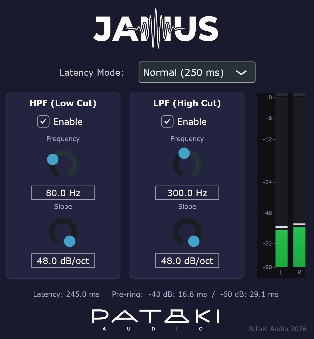
Quick Start
- Unzip and copy the
Janus.vst3folder toC:\Program Files\Common Files\VST3\on Windows, or to~/.vst3/on Linux (or your host's VST3 folder), then rescan plugins. Updating from 1.2.1 or earlier on Windows: delete the old single-fileJanus.vst3first. - Insert Janus on a stereo path. It opens with both sections disabled, so it passes audio through unchanged apart from its latency.
- Leave Latency Mode on Normal to begin with.
- Tick Enable on the section you need. Set Frequency to your crossover point and Slope to the steepness you want; 24 dB/oct (LR4) is the classic choice. At 48 dB/oct and above you can tick ERF for a shorter-ringing transition; see LR or ERF?
- Read the line at the bottom: Latency is what Janus reports to your host, and Pre-ring is how long the filter rings before a transient at −40 and −60 dB.
- For a full crossover, use one instance per band, with the same latency mode and matched frequency and slope at each crossover point. See Building a Crossover.
Controls
Sets the time budget for the filter's impulse response, and with it the latency Janus reports to the host. A longer budget allows lower crossover frequencies and steeper slopes; a shorter one keeps latency down. See Latency Modes & Limits.
Latency changes only when you change this mode. Moving frequency, slope or the enable switches never changes the reported latency, so your host's delay compensation never has to recalculate mid-playback.
Switches a section in or out. HPF only makes a high-pass, for a tweeter or the top band. LPF only makes a low-pass, for a woofer or the bottom band. Both makes a band-pass, for a midrange.
With both sections off, Janus is a pure delay matching its reported latency. That makes it a clean, time-aligned bypass, and a handy delay-matched path for a full-range channel that sits alongside crossed-over ones.
The crossover frequency: the point where the filter is 6 dB down. You can drag the knob, use the scroll wheel, or type a value into the box below it, in Hz or kHz (2.5k works).
How low you can go depends on the slope and the latency mode. If a setting would need more pre-ring than the mode allows, Janus stops the knob at the lowest valid frequency. Hovering over the knob then shows why, for example "Limited to 155.6 Hz at 24.0 dB/oct in Low latency mode. Switch to Normal mode for full range."
How steeply the filter rolls off beyond the crossover frequency. The classic Linkwitz-Riley orders fall at 12 (LR2), 24 (LR4), 48 (LR8) and 96 dB/oct (LR16), but any value in between is valid and behaves the same way: −6 dB at the crossover frequency, summing flat with its complement.
Steeper slopes reduce the overlap between drivers. That helps with drivers that have break-up modes, limited excursion or poor off-axis behaviour near the crossover. The cost is longer pre-ringing, which grows in proportion to slope ÷ frequency.
Replaces the section's Linkwitz-Riley transition with a Gaussian (erf) one. The slope knob keeps its meaning: half an octave into the stopband, the ERF filter has exactly the attenuation LR has at the same slope. Beyond that it falls away much faster, and it rings less before transients. See LR or ERF? for the numbers.
Below 48 dB/oct the switch is greyed out and the section stays Linkwitz-Riley, because there the Gaussian would ring as long as LR or longer. The switch keeps its setting while greyed, so raising the slope back to 48 dB/oct brings ERF back.
Latency Modes & Limits
A linear-phase filter is symmetric in time: whatever ringing it has after a transient, it has the same amount before it. The ringing lasts longer at lower frequencies and with steeper slopes. Each latency mode gives the filter a fixed amount of time on each side of its peak:
| Mode | Time budget each side | Reported latency | Typical use |
|---|---|---|---|
| Low | 45 ms | ≈ 50 ms | Mid/high crossovers, video playback |
| Normal | 245 ms | ≈ 250 ms | Most music playback crossovers |
| Maximum | 695 ms | ≈ 700 ms | Subwoofer and deep-bass crossovers, steep slopes |
The exact reported latency is the time budget plus a small amount that depends on your host's buffer size. The readout at the bottom of the window shows the precise figure.
Lowest crossover frequency per mode
Janus will not let a filter need more pre-ring than its mode allows. These are the lowest frequencies you can set:
| Slope | Low | Normal | Maximum |
|---|---|---|---|
| 12 dB/oct | 78 Hz | 14 Hz | 10 Hz |
| 24 dB/oct | 156 Hz | 29 Hz | 10 Hz |
| 48 dB/oct | 311 Hz | 57 Hz | 20 Hz |
| 96 dB/oct | 622 Hz | 114 Hz | 40 Hz |
The limit is conservative. Even at the extreme corner of each mode, at 96 dB/oct, the measured −60 dB pre-ring uses only about 17% of the budget. The limit applies to each enabled section separately; disabled sections are ignored.
Switching to a shorter mode moves your frequencies up. If a section is set below the new mode's limit, Janus raises its frequency to the lowest valid value. The same happens when a saved project is reopened. Switching back does not restore the old value, so check your frequencies after changing mode.
Building a Crossover
Use one Janus instance per band, each feeding its own amplifier channel. Three rules make the bands add up to a flat whole:
- Same latency mode in every band. All instances then have exactly the same delay, so the bands stay time-aligned without any extra compensation. Choose the mode needed by the lowest crossover point, and use it everywhere.
- Matched frequency at each crossover point. The low-pass of the band below and the high-pass of the band above must use the same frequency.
- Matched slope and shape at each crossover point. They must also use the same slope, and either both LR or both ERF. Different slopes or shapes on either side of a crossover point will not sum flat. Different crossover points can use different slopes and shapes.
Two-way example
Woofer   LPF  2.2 kHz  24 dB/oct      (HPF off)
Tweeter  HPF  2.2 kHz  24 dB/oct      (LPF off)
Mode     Normal on both
Three-way example
Woofer   LPF  300 Hz   24 dB/oct                       (HPF off)
Mid      HPF  300 Hz   24 dB/oct  +  LPF 3 kHz  48 dB/oct
Tweeter  HPF  3 kHz    48 dB/oct                       (LPF off)
Mode     Normal on all three
With crossover points about a decade apart, as here, the three filters sum flat to within a thousandth of a dB. The one thing to watch is spacing. The woofer's low-pass and the tweeter's high-pass still overlap slightly in the middle of the mid band, and that overlap adds a small rise between the two crossover points. It is about +0.9 dB with the points one octave apart at 12 dB/oct, and +0.3 dB at 24 dB/oct or two octaves apart. Steeper slopes or wider spacing make it vanish.
Hosting the bands
Janus filters channels 1 and 2 of whatever bus it is given. On a wider bus, such as JRiver's 8- or 12-channel output, all other channels pass through untouched. To give each band its own filter on a multichannel rig, run one Janus per channel pair inside MetaHost, one column per band. In a DAW, put each instance on its own stereo track or send.
Janus is purely a crossover filter. Driver level matching, time alignment between drivers and correction EQ belong elsewhere in the chain, for example in Chronos with a measured correction filter.
LR or ERF?
A Linkwitz-Riley transition is a single curve: the slope you choose sets both how sharp the knee is at the crossover frequency and how fast the filter falls far from it. That is what makes steep LR filters ring: a sharp knee means a long, slowly decaying ring before and after every transient.
The ERF transition separates the two. Its knee is a little softer, and its stopband does not settle at a fixed number of dB per octave: it keeps getting steeper. Janus matches the two shapes where it matters for driver protection, half an octave into the stopband, so at any slope from 48 dB/oct you get:
| 48 dB/oct LR | 48 dB/oct ERF | 96 dB/oct LR | 96 dB/oct ERF | |
|---|---|---|---|---|
| ¼ octave out | −14.0 dB | −13.3 dB | −24.6 dB | −20.8 dB |
| ½ octave out | −24.6 dB | −24.6 dB | −48.2 dB | −48.2 dB |
| 1 octave out | −48 dB | −61 dB | −96 dB | −146 dB |
| Pre-ring at 300 Hz, −40 / −60 dB | 6.0 / 8.4 ms | 4.9 / 7.3 ms | 9.5 / 16.2 ms | 7.9 / 11.7 ms |
| Pre-ring at 2.5 kHz, −40 / −60 dB | 0.7 / 1.0 ms | 0.6 / 0.9 ms | 1.1 / 1.9 ms | 0.9 / 1.4 ms |
The pre-ring figures are for a single section. They scale with 1/frequency, so the percentages hold at any crossover point. Like LR, an ERF high-pass and an ERF low-pass at the same frequency and slope add up to exactly one, so ERF crossovers sum flat and stay linear phase.
When to use it. ERF pays off most at low crossover points with steep slopes, where LR pre-ringing gets long enough to matter, such as a woofer/midrange crossover at a few hundred Hz. At a midrange/tweeter crossover in the kHz range both shapes ring for only a millisecond or two, so the choice makes little audible difference there; the slightly softer ERF knee is a fair trade for its much deeper stopband.
Why not below 48 dB/oct? At gentler slopes the Gaussian's wide transition rings as long as LR or longer (at 24 dB/oct about 20% longer at −60 dB), so Janus keeps those slopes Linkwitz-Riley.
Readout, Graph & Meter
Latency and pre-ring
The line along the bottom shows Latency, the delay reported to your host in milliseconds. It also shows Pre-ring at two thresholds: the time from where the filter's impulse response first rises above −40 dB, and −60 dB, relative to its peak, until the peak itself. These figures are measured on the filter actually being used, not estimated from a formula, so they update every time you change a setting.
As a rough guide, the −40 dB figure tells you what is most likely to be audible as a pre-echo on sharp transients. The −60 dB figure shows how far the filter really extends.
On a band-pass instance the figures describe the combined filter, so they are set by whichever section rings longer, which is nearly always the lower-frequency one. Ringing time scales with 1/frequency, so a 400 Hz high-pass rings several times longer than a 2.6 kHz low-pass at the same slope. Switching ERF on the low-pass of such a band then leaves the readout unchanged even though the low-pass itself now rings less, while switching ERF on the high-pass shortens it. The graph and the audio change either way.
Response graph
The graph shows this instance's magnitude response from 10 Hz to 20 kHz and +6 to −90 dB, and redraws as you change any setting, including from host automation. A white dot marks each crossover frequency on the curve. Each enabled section also shows its complement as a faint dashed line: the response the neighbouring band must have at that crossover point for the two to sum flat. When the next instance's solid curve lies on that dashed line, the crossover point is set up correctly.
The graph is drawn from the same function the filter is designed from, and is checked against the delivered impulse response to within 0.00001 dB, so it shows what you hear, not an approximation.
Output meter
A stereo peak meter for the filtered output of channels 1 and 2, from −90 to 0 dBFS. The upper half (0 to −24 dB) is linear in dB for detail; the lower half is compressed. Green, yellow and red zones change at −12 and −3 dBFS.
- The bars respond instantly and fall back at 17 dB per second.
- A white peak-hold line stays for 1.5 s, then falls at the same rate.
- The small segment above each bar turns red when a sample reaches 0 dBFS and stays lit for 3 s. Click the meter to clear it sooner.
How It Works
Janus designs each filter directly in the frequency domain from the Linkwitz-Riley magnitude law, with s the slope in dB/oct:
LPF:  |H(f)| = 1 / (1 + (f / fc)^(s/6))
HPF:  |H(f)| = 1 / (1 + (fc / f)^(s/6))
With ERF on, a section uses a Gaussian transition in log-frequency instead, with σ solved so the attenuation half an octave out matches LR at slope s:
LPF:  |H(f)| = ½ · erfc( ln(f / fc) / (σ·√2) )
HPF:  |H(f)| = ½ · erfc( −ln(f / fc) / (σ·√2) )
At f = fc both shapes are exactly 0.5 (−6 dB), and the LPF and HPF at the same fc, s and shape always add up to exactly 1. That identity is why the bands sum flat. With both sections enabled the two targets are multiplied, giving one combined band-pass response. Each instance therefore runs one filter per channel, never two in series.
- Zero phase, then delayed. The target has no phase of its own. An inverse FFT gives a perfectly symmetric impulse response, centred in the buffer, which is what makes the result linear phase.
- Fixed length per mode. The impulse response is cut to exactly twice the mode's time budget, with a short symmetric taper at the ends. Its length depends only on the mode and sample rate, so the delay never changes when you adjust frequency or slope.
- Built off the audio thread. Filter design runs on a background thread. Rapid knob movements are gathered into a single redesign, and the new filter is handed to the audio thread without locks or memory allocation.
- Click-free changes. Each new filter is crossfaded in over 30 ms, so moving a knob or toggling a section during playback never clicks.
- 64-bit throughout. In a 64-bit host such as JRiver, filter design and convolution both run in double precision, checked against direct convolution at about 3 × 10⁻¹⁶ relative error. In a 32-bit host the same filter runs through a single-precision convolver.
Specifications
- Plugin format
- VST3
- OS support
- Windows 10+ (64-bit); Linux x64 with glibc 2.28+ (Ubuntu 20.04+, Debian 10+, RHEL 8+); Linux ARM64 with glibc 2.28+ (Raspberry Pi OS 64-bit on Pi 4/5, Ubuntu 20.04+ arm64)
- Channels
- Stereo; on wider buses channels 1–2 are filtered and the rest pass through (input and output widths must match)
- Sample rates
- 44.1 – 192 kHz; frequency response and latency identical across rates
- Filter type
- Linear-phase FIR, Linkwitz-Riley magnitude (−6 dB at fc); optional ERF (Gaussian) transition per section from 48 dB/oct
- Sections
- HPF + LPF per instance; HPF only, LPF only, band-pass, or pure delay
- Frequency
- 10 Hz – 20 kHz, log, limited by slope and latency mode
- Slope
- 1 – 96 dB/oct, 0.1 dB steps
- Latency
- ≈ 50 / 250 / 700 ms (Low / Normal / Maximum), reported to host; independent of filter settings
- Precision
- 64-bit double-precision design and convolution; 32-bit path for 32-bit hosts
- Parameter changes
- 30 ms crossfade, no clicks
- Parameters
- HPF Enable / Frequency / Slope / ERF, LPF Enable / Frequency / Slope / ERF, Latency Mode — all automatable
- Display
- Live response graph, 10 Hz – 20 kHz, +6 to −90 dB
- Bundle size
- ~6 MB
- License
- Donationware — pay what you want, including €0
FAQ & Troubleshooting
The frequency knob won't go any lower.
That setting would need more pre-ring than the current latency mode allows. Hover over the knob to see the limit, then either switch to a longer mode, reduce the slope, or accept the higher frequency. The table in §04 shows the limits.
Why so much latency?
A linear-phase filter's delay has to be at least as long as its pre-ring, and low, steep crossovers ring for a long time. For music playback the host compensates and you never notice it. For video, use Low mode where your crossover points allow it, or set your player's audio/video offset to match.
Will I hear the pre-ringing?
Usually not at sensible settings: the pre-ring sits in a narrow band around the crossover frequency, at low level, and is largely masked. It becomes more audible at low frequencies with very steep slopes. Watch the −40 dB figure. If it is long and you hear a soft "swish" before kick drums or piano attacks, try a gentler slope.
Is there a bypass?
Turn both Enable switches off. Janus then passes audio through with exactly its reported delay, so the timing of the rest of your chain stays put. Your host's own bypass works too, but not every host keeps the delay matched when bypassing.
Can I use a non-standard slope like 30 dB/oct?
Yes. Every slope follows the same law: −6 dB at the crossover frequency, and a flat sum with a matching opposite filter. The classic LR2/LR4/LR8/LR16 values are just familiar points along a continuous range.
Should I switch ERF on?
If you use 48 dB/oct or steeper, it is worth trying, especially at low crossover points where LR pre-ringing gets long. Switch it on for both sides of a crossover point. At gentler slopes it is not available, because it would not help. See §06.
Ticking ERF doesn't change the pre-ring figures.
On a band-pass instance the readout shows the longer-ringing section, nearly always the lower-frequency one. ERF on the higher-frequency section still works, as the graph shows, but its shorter ring is hidden inside the other one. See §07. Also check the slope: below 48 dB/oct the switch is greyed out and has no effect.
My bands don't sum flat.
Check, in order: the same latency mode on every instance; the same frequency, slope and shape (LR or ERF) on both sides of each crossover point; and that no frequency was silently raised by a mode change (see the callout in §04). The dashed complement curves in the graph make the first two easy to check. If those are right, the remaining differences are in the drivers and the room, not in Janus.
I put Janus on a 12-channel JRiver bus and only the front pair is filtered.
That's by design: Janus filters channels 1 and 2 and passes the rest through. For per-band filtering on a multichannel output, use MetaHost with one Janus per channel pair.
Something went wrong. What should I send with a bug report?
If Janus hits an internal error it outputs silence instead of crashing the host, and writes a log to %LOCALAPPDATA%\PatakiAudio\Janus\trace.log. Send that file, your host, sample rate, buffer size and settings to info@patakiaudio.com.